Industries we have served

Ultrasonic Testing
Home » NDT Services » Ultrasonic Testing
As the name implies, ultrasonic refers to an NDT method, which uses sounds having frequencies beyond those audible by human ears. Sounds having frequencies about 50 kHz to 100 kHz are commonly used for inspections of nonmetallic materials, whereas those with frequencies between 0.5 MHz up to 10 MHz are commonly used for inspections of metallic materials.
Ultrasonic testing (UT) method uses high frequency sound waves (ultrasounds) to measure geometric and physical properties in materials. Ultrasounds travel in different materials at different velocities. The ultrasound wave will continue to travel through the material at a given velocity and does not return back unless it hits a reflector. Reflector is considered any boundary between two different materials, or a flaw.
The ultrasound generator (transducer) emits waves and in the same position receives reflected sounds (if any). Comparing both signals (emitted and reflected) the position of the defect and its size can be measured. The UT can be used on civil engineering equipments, outside metallic parts, to verify the granulation of road covering or of concrete.
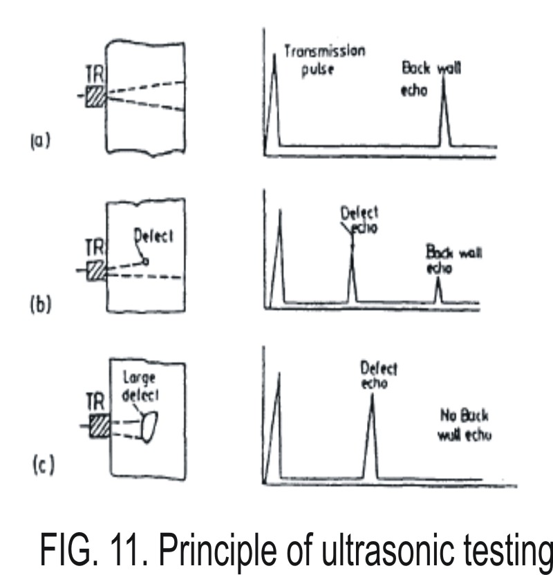
High frequency sound waves are introduced into a material and they are reflected back from surfaces or flaws. Reflected sound energy is displayed versus time, and inspector can visualize a cross section of the specimen showing the depth of features that reflect sound (Fig. 11).
(a) defect free specimen; (b) specimen with small defect; (c) specimen with large defect
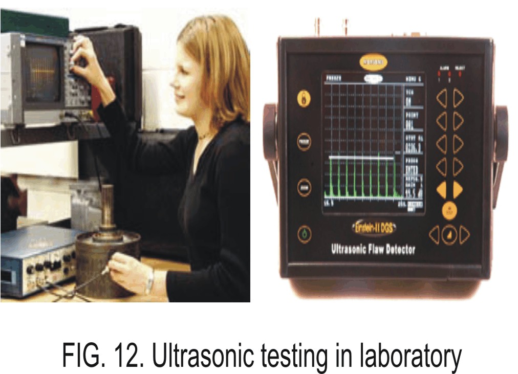
As in the case of radiography, ultrasonic is an NDT method that is used for detecting internal discontinuity. In ultrasonic inspection, sounds are generated by the use transducers that are made of materials exhibiting piezoelectric effect. Materials exhibiting piezoelectric effect are capable of converting electrical energy into sound energy and vise versa. Typical example of such a material is quartz. When a quartz crystal is cut in certain orientation and thickness it is capable of generating sounds appropriates for ultrasonic inspections. Depending upon the orientation of crystal cutting, sounds generated by quartz can be of the longitudinal or transverse modes. Figure 10 shows ultrasonic testing in laboratory.
During the inspection, sound generated by a transducer is transmitted into the material to be inspected via couplant. This sound travels in the material with a speed that depends on the type of material. For example, longitudinal waves travel at speeds of 5960 m/s and 6400 m/s in steel and aluminum respectively. When there is no discontinuity in the material, sound continues to travel until it encounters the backwall of the material.
At the backwall, sound is reflected and continues to travel until it reaches the transducer. At this transducer, piezoelectric converts sound energy into electrical pulse. The pulse is then amplified and presented on the screen as a backwall signal or backwall echo (Fig. 12).
However, if there is a discontinuity in the material, a portion of sound energy is reflected by this discontinuity whereas another portion continues to travel until it reaches backwall and reflected. Under these circumstances, a portion of sound that was reflected by the discontinuity reaches the transducer first and followed by those reflected by the backwall. In both cases sound energies are converted into electrical signals which then are displayed on the ultrasonic flaw detector screen as backwall signal and signal due to discontinuity. By properly calibrating the equipment, both the position of discontinuity with respect to the position of backwall and the size of discontinuity can be determined.
The fact that ultrasonic does not present any potential hazard to the operator makes this method as a good competitor for radiography method. However, highly skillful and experience operators are required to allow correct interpretation of the test results. Unlike in the case of radiography where the results are presented in the pictorial forms, results of ultrasonic inspections are purely in the form of electrical signal. Knowledge about the material, correct movement of the transducer and proper time base calibration is absolutely necessary for correct assessment of the test results.
More sophisticated ultrasonic equipment is currently available which allow results to be presented in 2D or 3D dimensions. This development provides greater strength to ultrasonic method in its rivalry against radiographic method.
The advantages and limitations of ultrasonic methods are as follows:
Advantages
- Requires only one side accessibility
- Capable of detecting internal defect
- Not hazardous
- Applicable for thickness measurement, detection of discontinuity, and determination of material properties
- Can provide the size of discontinuity detected
- Very sensitive to planar type discontinuity
- Suitable for automation
- Applicable for thick materials
- Equipment are mostly portable and suitable for field inspection
Limitations
- Not capable of detecting defect whose plane is parallel to the direction of sound beam
- Require the use of couplant to enhance sound transmission
- Require calibration blocks and reference standards
- Require highly skillful and experience operator
- Not so reliable for surface and subsurface discontinuity due to interference between initial pulse and signal due to discontinuity.