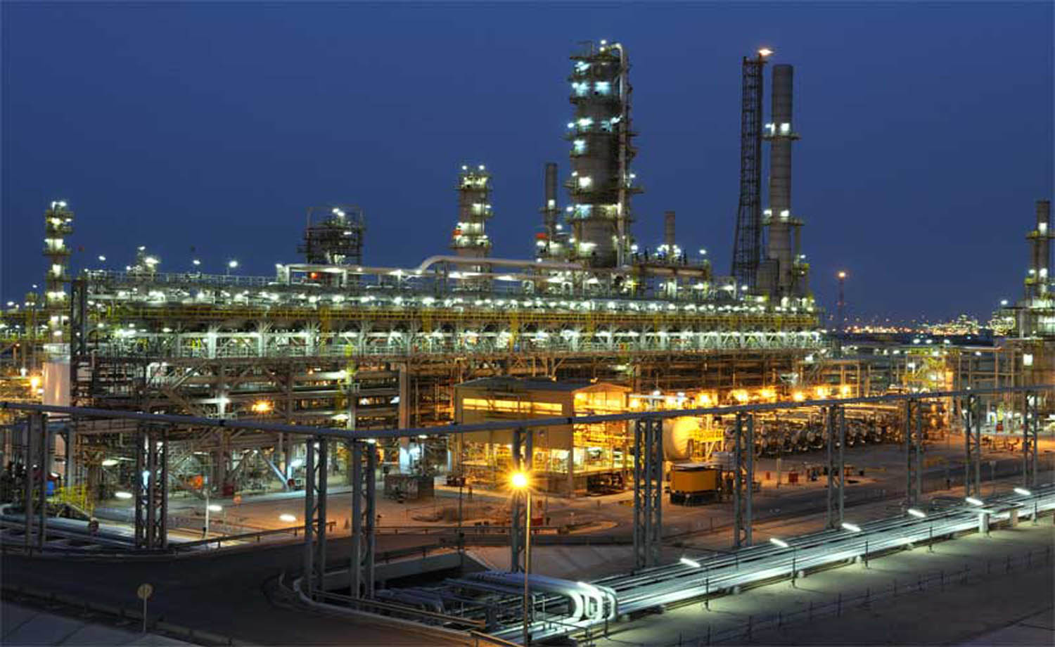
Industries we have served
TOFD, Time Off Flight Diffraction
Home » NDT Services » TOFD, Time Off Flight Diffraction
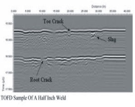
Time of Flight Diffraction or TOFD, is one of the most promising ultrasonic techniques for the examination of welds on pressure vessels in lieu of radiography; for pipe weld quality or crack detection and also weld root erosion. TOFD is a computerized ultrasonic system able to scan, store, and evaluate indications in terms of height (through wall thickness), length and position, with a degree of accuracy and speed never achieved with other ultrasonic techniques.
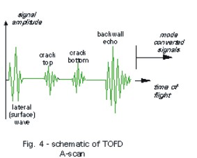
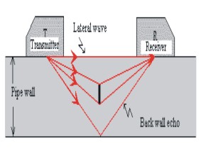
Theory – TOFD consists of a separate ultrasonic transmitter & receiver. The probes are aimed at the same point in the weld volume. The entire weld is then flooded with ultrasound allowing inspection of the weld. After emission of a compressional wave from the transmitter, the first signal to arrive at the receiver is the lateral wave or OD wave which represnts the outer surface or OD. In the absence of defects, the second signal to arrive at the receiver is the L-wave backwall echo which represents the inner surface or ID. When a flaw is present, a diffracted signal is generated at the upper tip of a defect and will arrive before the signal generated at the lower tip of a defect. With a time of flight of each flight path, ultrasonic velocity and the spatial relationship of the two probes, the location and height of the defects can be accurately calculated. Gray scale imaging techniques are applied to the RF (AC) signal phase and enables weld integrity to be observed in real time.
Visual inspection is normally performed by using naked eyes. Its effectiveness may be improved with the aid of special tools. Tools include fiberscopes, borescopes, magnifying glasses and mirrors. In both cases, inspections are limited only to areas that can be directly seen by the eyes.
However, with the availability of more sophisticated equipment known as borescope, visual inspection can be extended to cover remote areas that under normal circumstances cannot be reached by naked eyes. Defects such as corrosion in boiler tube, which cannot be seen with naked eyes can easily be detected and recorded by using such equipment.
Although considered as the simplest method of NDT, such an inspection must be carried out by personnel with an adequate vision. Knowledge and experience related to components are also necessary to allow him to make correct assessment regarding the status of the components.
The advantages of TOFD
So far, the following advantages have been recorded:
- TOFD defect detection does not depend on the defect orientation, in contrast to the pulse echo technique.
- Defect height can be exactly determined, thus most suitable for monitoring growth or changes in known defects.
- The inspection results are immediately available, as is a permanent record.
- Because of the high-test speed the costs are less than those for radiography for wall thickness above 25 mm. It is possible to perform faster scans.
- TOFD save costs, if applied during construction, since it is possible to distinguish pre-service and in-service defects. That means the unit can stay longer in production, and is safe.
- High probability of defect detection .
- Most efficient for inspection of thick-walled vessels where X & Gamma ray would require too much time.
The disadvantages of TOFD
The disadvantages of the TOFD method so far have been found are mentioned in the below:
- Sensitivity level: If the instrument sensitivity (gain) is set on very low level, the TOFD image would display no diffracted echo. If the instrument sensitivity is set just above electronic noise level, the TOFD image will display a lot of diffracted echoes which are caused by very small inhomogeneities of the weld seam and does not mean that the weld is really bad.
- A disadvantage of TOFD is that the gain must be very high, which produces a very high back wall echo and it is not suitable for coarse grained materials.
- There is a dead zone for defect detection under the surface. It means, defects close to the surface could not be detected. This may be compensated by MPT (Magnetic Particle Test) or test with creeping wave probe.
- Minimum thickness requirement is 6mm with diameter of 4″. No limitation on maximum thickness, it could be several hundreds mili-meters.
- Cannot be applied on coarse-grain weldment e.g. austenitic stainless steel and Inconel.